Another old project that someone might find useful.
This is a tool I wrote to help create schematics from manufactured PCB’s.
Basically it will take a top and bottom image of a circuit board and re-map the images to the same scale and orientation so that it’s easier to create a schematic.
Here is basic usage example.
When the program loads, you’re presented with 3 tabs. On the first tab ‘Load Image A’ this button will open a file dialog to pick an image. The supported image types are: bmp, gif, jpeg,png, tga and webp.
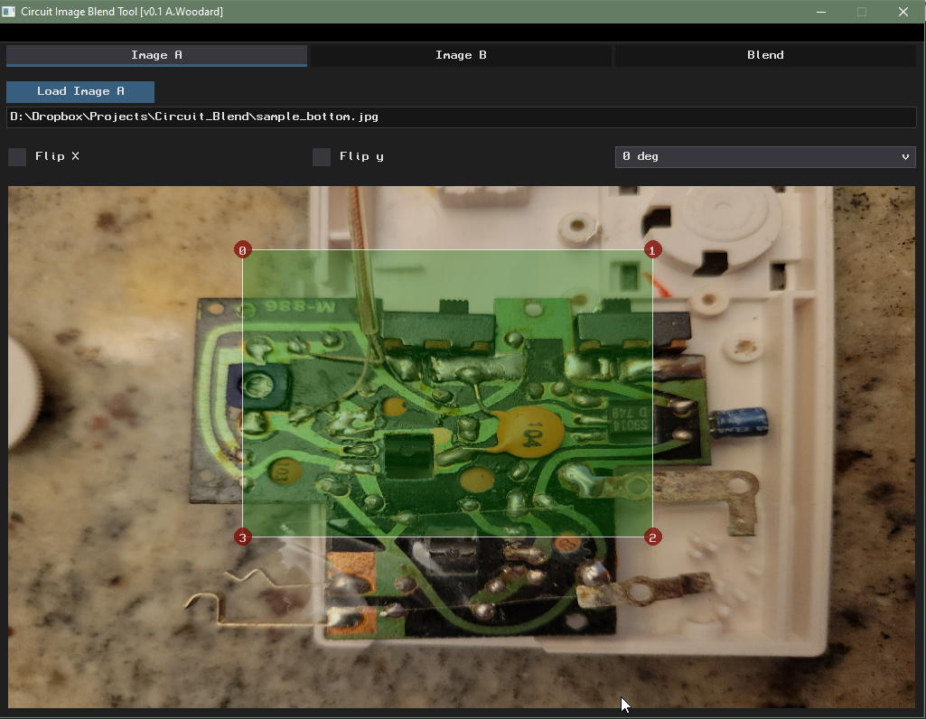
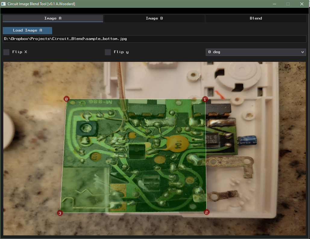
When the Image is loaded, you can flip or rotate the image to get the orientation that’s preferred. There is also a rectangle with 4 control points. Move these control points cover the pcb area of interest.
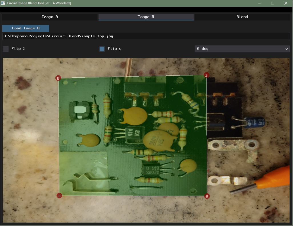
The same process is used for ‘image B’. Notice in the example that ‘Flip Y’ checkbox is checked so that both the A and B images have a matching orientation.
Once both images are loaded, the ‘Blend’ tab will be available, There is a slider at the top which will adjust the blend of the 2 images front and back.
There are also some hot keys to control the blending without using the mouse.
A,S,D with set the blending levels to 25%, 50% and 75%.
Z,X,C will adjust the blending levels to 0%,50%,100%.
The blend tab also has a primitive drawing tool for making markers on the blended image.
The program and included Blitzmax source code can download from HERE.